«- back to print version table of contents
Weak Echo Region
Detection
A Weak Echo Region (WER) refers to an area of weak radar returns at low levels on the inflow side of a thunderstorm. A WER is bounded by stronger radar echoes above and on one side. In low-level PPI scans, the WER is often associated with a concave strong reflectivity gradient on the low-level inflow side. A WER is bounded by stronger echoes only on one side. If a WER is bounded by stronger echoes on more than one side, or is surrounded by stronger echoes, the signature is referred to as a BWER (Bounded Weak Echo Region).
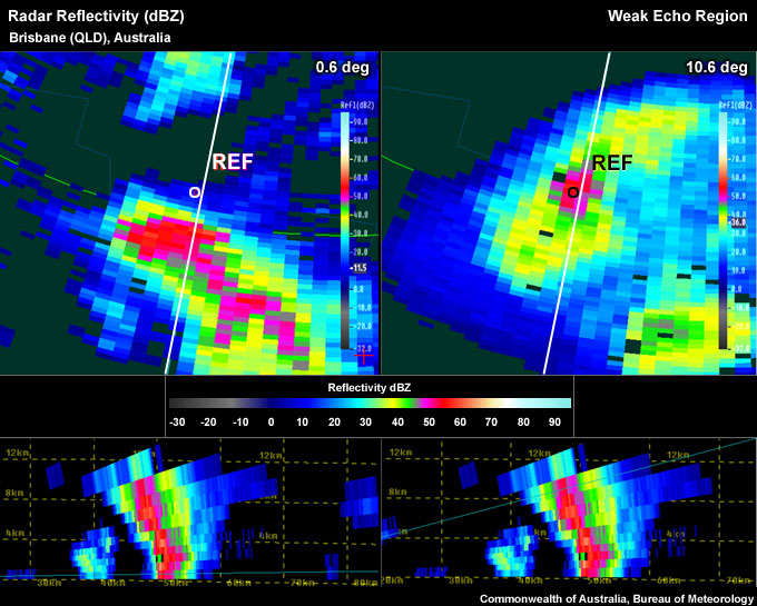
The lowest elevation scan of a storm on the PPI (left) and a PPI at the storm top level (right). A reference point marking the storm top location is located well north of the low level core. The WER can also be seen in the RHI display, under the sloping reflectivity core.
To determine if the signature you are seeing is a Weak Echo Region, use the following approach:
Reflectivity: PPI/Plan View
Determining the inflow/updraft location:
- Step up in elevation scans until you run out of >50 dBZ echoes.
- Step down one elevation scan.
- Centre cursor on the upshear side of the 50 dBZ+ core (this is to account for storm movement between the low-level and high-level radar scans in the presence of strong winds aloft).
- Set a reference point (this marks the approximate storm top).
- Step down to the lowest elevation scan.
- Is the reference point on the edge of the lower core or outside the core altogether? (see example above) If yes, a WER is present.
Note: It is possible to find more than one WER, in such cases as a splitting cell or a multicellular system.
Reflectivity: RHI/Cross-Section
- Follow steps 1-5 from Reflectivity: PPI/Plan View (see above)
- Choose the most direct cross section from the reflectivity core at the lowest tilt to the reference point you set in the upper levels, representing the upper level core. Note: You may need to use an arbitrary (rather than a radial) cross section if you cannot place a standard radial line (originating at the radar location) through the storm top marker and the nearest low-level core.
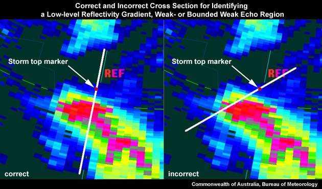
On the left is a correctly placed cross section for identifying a WER, as the most direct path from the low level reflectivity core to the location of the storm top marker. On the right is an example of an incorrectly placed cross section.
- Is there an area of weak echoes bounded by strong echoes above and on one side (see Figure 1)? If yes, a WER is present.
Potential Difficulties in Detection
- Low-topped storms – If low equilibrium level (this is often the tropopause) is present, the thunderstorm is low-topped and vertically compressing the WER signature making it difficult to detect. This may be a particularly serious issue far away from the radar.
- Radar sampling
- Radar not "aligned" well with the storm. The radial from the radar does not allow a direct line from the storm top to the low-level core. An arbitrary (non-radial) cross section should be used in such a case, which is an interpolated RHI with smoothed data.
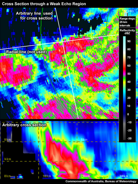
Arbitrary cross section through a WER that is sloping across a radial radar beam.
-
- The thunderstorm is too far away from the radar and the beam overshoots the signature.
- The thunderstorm is too close
Examples of Weak Echo Regions

A WER is evident in the PPI when comparing a low-level scan with an upper-level scan. Notice the reference point centred on the upper level core, on the right, is well displaced from the low-level core, on the left.
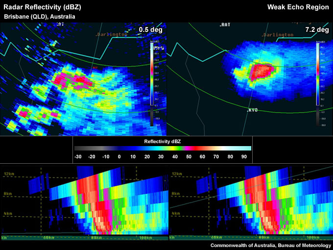
A WER similar to Example 1, but with a larger overhang evident in the RHI display
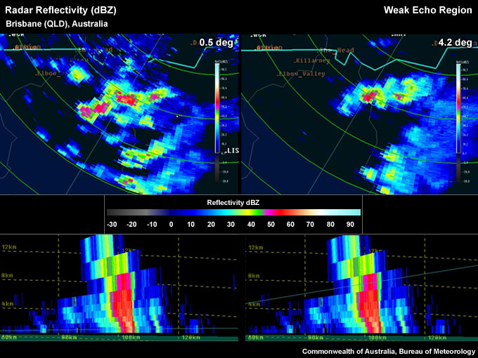
A WER with a small overhang is seen in the RHI.
WER Look–a–Likes
- Fast moving storm – This look-a-like can give the impression of a WER. The thunderstorm moves so quickly towards or away from the radar that during the time the volume scan is built at each elevation, the storm has moved enough to give the impression of a horizontal core displacement with height. Notice the steplike appearance of the core through the depth of the storm.
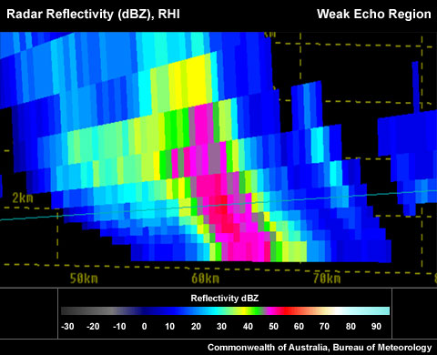
Fast moving storm with a step-like appearance of the core of the storm, creating a false WER.
- Overhang is not on the updraft/inflow side – It is important to be sure the WER is located on the updraft/inflow flank of the thunderstorm. This should not be an issue if you use the detection method explained above. A WER is a signature suggesting storm severity based on the likely association of an echo overhang with a strong updraft. There could be many reasons for finding a false WER, including the other look-a-likes in this section.
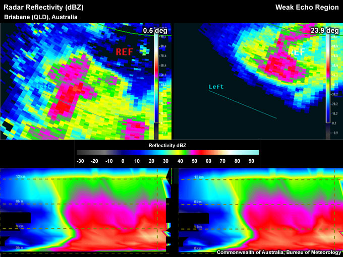
Arbitrary cross section placed across a core that is well removed from the dominating updraft of this storm (storm top shown in the right panel).
- Elevated core from a separate updraft – More often than not storms are multicellular in nature with several updrafts located close to each other. Sometimes this can lead to confusion while interrogating storms, connecting elevated cores that are slightly displaced to a low level core and assuming it is a single core with a WER.
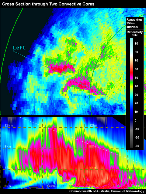
This cross section has been placed in such a way that it intersects at least two major updrafts, indicated by the substantial high-level (~9 km) cores in the PPI pane. The result looks like a single (complex) WER, but is actually the combined core of multiple updrafts.
- Overspreading anvil – This should rarely be confused with a WER, as anvils tend to have weaker reflectivities, than those typically found within potentially severe thunderstorm cores.
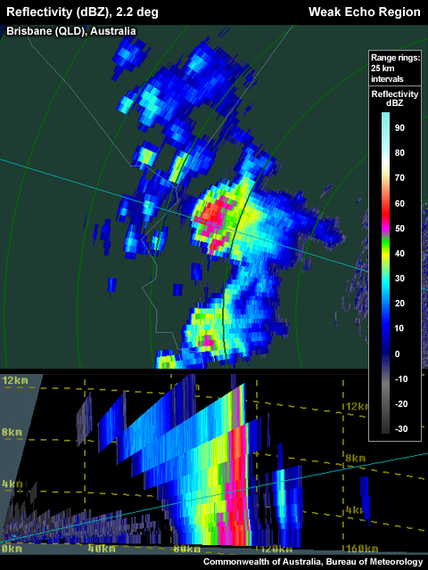
The RHI panel (lower panel) shows an anvil extending to the left of the main core of the storm. The weak echo area below the anvil is clearly not a WER.
Conceptual Model
A Weak Echo Region (WER) is used as one of many signatures that may indicate thunderstorm severity. The presence of a WER indicates that the thunderstorm possesses a strong updraft with diverging flow at the updraft summit. The hydrometeors within this divergent flow are forced outward into a thick anvil from where they descend into the approaching environmental winds. The descending precipitation, apparent on radar as a sloping echo overhang, is swept back toward the storm's updraft flank where later the hydrometeors eventually reach the surface. As the precipitation falls from the divergence signature aloft it is replaced with more precipitation diverging from the continuing updraft, producing a longer-lived signature. Hail growth is likely, providing the updraft extends past the freezing level into the -10°C to -30°C layer. In addition, a strong updraft can suspend large amounts of precipitation, especially hail, that can travel across and through the updraft without falling back through the updraft. The precipitation instead descends within the sloping echo overhang and the weaker portions of the updraft, creating a weak echo region below the overhang.
A strong updraft increases the chances of all four severe convective hazards to be produced. Large hail and damaging winds are most likely to occur and are both used as criteria to determine a severe thunderstorm in Australia. Damaging winds are included, as a strong updraft is likely to produce a strong downdraft, especially if large hail is expected.
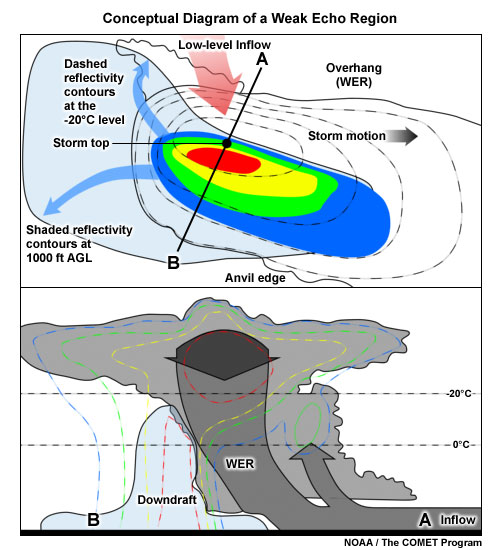
A conceptual model of the structure of a WER within a severe thunderstorm (northern hemisphere example). The top image shows a plan view of the storm low-level (shaded reflectivity contours) and the -20°C level (dashed reflectivity contours). The blue arrows represent the upper divergence. The red arrow represents the inflow. The lower image shows a cross section of the storm, with the reflectivity contours dashed. The grey arrows represent the updraft with the blue shaded region the downdraft.
Determining Thunderstorm Classification
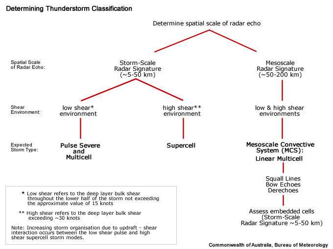
WERs are mainly found in severe storms in sheared environments, especially in supercells. Occasionally small WERs can be found in more pulse-driven severe thunderstorms, especially if some amount of weak deep-layer shear is present, although these WERs tend to be short-lived. Multicell modes, both cluster and linear, can also produce WERs, as their composition can include strong individual cells.
To help determine the classification of the thunderstorm you are observing, use the following flow chart to help diagnose which thunderstorm conceptual model you should consider more closely.
Diagnosis
Once you have confidently identified a Weak Echo Region signature, this section will help you estimate the storm severity associated with it. Generally, the spatial and temporal scales of a signature are loosely related to the updraft strength. In other words, the larger and/or more long–lived the signature, the stronger the updraft that produced it. In velocity-based signatures, updraft severity can usually also be gauged by the magnitude of the measured radial velocities. Examining a stormís overall temporal evolution will suggest whether the storm is becoming more or less severe. Radar signatures and associated storm developments can also be time-shifted relative to each other, as is the case in supercell tornadoes that occur during the collapse of the parent storm.
When comparing signatures to diagnose relative severity, keep in mind that it is assumed that signatures are sampled at equal ranges from the radar. Otherwise, a storm sampled at greater range (with a wider beam) can appear to be weak and/or weakening, while a storm sampled at a closer range (with a narrower beam) can appear to be strong and/or strengthening.
Degree of Severity
- Horizontal length of WER – The larger the distance between the overhang of upper-level 50 dBZ core from low level 50 dBZ core, the more vigorous the flow divergence and hydrometeor suspension would have to be. An unpublished U.S. Radar Climatology compiled by Les Lemon suggests that the minimum overhang length for a severe thunderstorm was around 4 km. (Lemon, personal correspondence). Below are two different examples of overhang distances in severe thunderstorms.
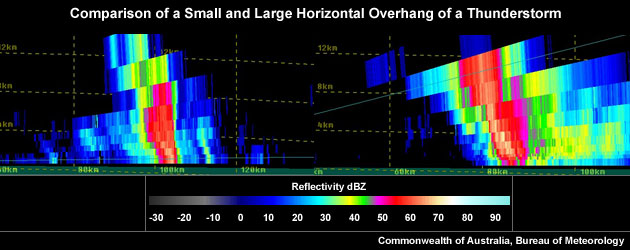
A comparatively small horizontal overhang of a thunderstorm core on the left and a comparatively large horizontal overhang of a thunderstorm core on the right.
- Longevity of the WER – The more persistent a WER, the more likely that the thunderstorm has persistently strong flow divergence. In that case, the storm would have a persistently strong updraft that allows hail embryos longer residence times in regions promoting hail growth, given that the updraft was embedded in the hail growth layer.
- Average dBZ of WER – The higher the average reflectivity in the core that shapes the WER, the larger the hydrometeors that are present, particularly large hail. The creation of large hydrometeors requires a strong updraft. For an updraft to be deemed strong, the suspended reflectivity values need to be at least 50 dBZ.
- Vertical depth of the WER – The larger the distance, H, between the ground and the main overhang aloft, the more likely the updraft summit divergence reaches into (or beyond) the ideal hail growth layer with supercooled liquid water droplets required for the production of large hail. Very tall WERs are more meaningful as an updraft strength proxy than short stubby ones, given both WERs are sampled equally by the radar and exist in the same storm environment.
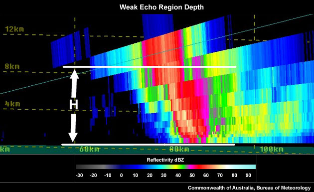
Weak Echo Region depth (H).
Considering all these aspects will help to determine overall whether you are dealing with a particularly significant WER signature. In the context of a severe thunderstorm warning decision, a significant WER should be counted as good evidence of a severe thunderstorm, but should be used in conjunction with other signatures and should always be considered in conjunction with near-storm environmental information and any severe weather reports.
Most Likely Convective Hazards
If a thunderstorm has been determined to be severe and possesses a WER of significance, the following severe weather should be considered to be included in the severe thunderstorm warning:
- Damaging winds – A WER is a representation of a strong updraft, with potential to produce a strong downdraft.
- Large hail – A strong updraft has the potential to produce large hail, providing the updraft extends into the hail growth layer (-10°C to -30°C). Consider the (wet bulb) freezing level height to identify the potential for hail melting as it descends to the ground.
See Conceptual Models for more details on why particular severe weather phenomena should be included.
References/Addendum
Lemon, L.R., 1980. Severe Thunderstorm Radar Identification Techniques and Warning Criteria. NOAA Tech. Memo. NWS